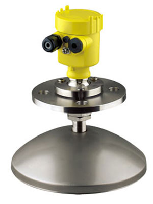
. Chemical Injection Skids
. High Pressure High Temperatrue (HPHT) Injection Systems
. Emergency Fire Pump Skids
. Hot Water Skids
. High Integrity Pressure Protection Skids (HIPPS)
. Deck Machinery
. Subsea HPU / Safe + EX HPU


. Well Head Control Panels Pneumatic / Hydraulic
. Valve Control Systems Hydraulic / Pneumatic / Electric
. Tank Management Systems
. Anti Heeling System
. Loading Computer Systems
. Vessel Management Systems / Alarm Monitoring Systems
. Fire and Gas Detection Systems
. Switchboards MV / LV


. Klopper Therm & Elmess Thermo System - Germany
. Dennis Nakakita Control Valve & Actuators - Spain
. Nakamura Accumulators - Japan
. OMV-INDOIL Industrial Valves - Europe
. SWTS Genset Turbines Drives Motor - a PON's Group
. Pepperl+Fuchs Industrial Sensors Isolated Barriers - Germany
. Den Holder - The Netherlands
 
 
Products & Services
 
  Offshore Systems  
 

replica watches uk

Mowe is one of Asia's most respected manufacturers & solution integrators/software (PLC) programmers/packagers. We are delivering our products replica orologi and services to Oil and Gas, Marine and Power industries. Mowe Group is headquarter in Singapore and has been in Marine and Offshore business for the past 22 years.


  Tank Management Systems  
     
 
MOWE Marine Tank Gauging
 

Substantial improvements in magnetostrictive liquid level sensors have recently been achieved, making them more attractive for use in automatic tank gauging (ATG) systems.

The improvements include flexible probes that are much easier to install and bottom-referenced probes which allow for more accurate readings for a storage tank. Such liquid level sensors are the key element in magnetostrictive tank gauges, which offer certain advantages over other types of automatic tank gauges.

Common types of ATGs include radar, magnetostrictive, hydrostatic, servo, float and tape.

Radar gauges are popular for their accuracy. They are particularly useful in gauging tars and other products not suitable for contact-type sensors.

On the other hand, for liquids that can accommodate a float, a bottom-references magnetostrictive tank gauge (MTG) can provide superior accuracy.

It is not affected by motion of the tank top. In addition, it can incorporate averaging temperature measurement into its liquid level probe. Hydrostatic tank gauges provide direct reading of mass but are less accurate for level. Servo-powered gauges can provide good accuracy but have a higher installed cost. Float operated tank gauges widely used in the past are losing popularity due to maintenance demands.


  Overview  


MOWE Tank Systems

  • RADAR systems – Frequency Modulation Continuous Wave (FMCW)
  • GUIDED RADAR systems
  • HYDROSTATIC PRESSURE systems
  • PNEUMATIC / Electro – Pneumatic Systems

Other Systems :

  • Loading Computer systems
  • Anti-heeling & Stability systems
  • Alarm & monitoring systems
  • Vapour Pressure, monitoring systems
  • Temperature monitoring systems 

Touch Screen and LCD computer based systems, to console mounted gauge systems.

Our systems are able to interface with traditional 4-20mA signals as well as Fieldbus, Modbus and other field signals and protocols.

Bloomfoss has the complete strength and capability to design and manufacture Tank Management Systems to meet IMO, CLASS requirements and fulfill owner expectations.


  Configuration  


Solution
 

A complete solution to our customers comprises of key components ranging from Field Instruments, data acquisition systems, processors and human machine interface (HMI) devices.

Our team of engineers with over 20 years of experience in Marine and offshore not just build systems, but design systems totally reliable and proven.


Radar Systems
 

Bloomfoss works closely with recognized radar equipment manufacturers to complete the Marine Radar Tank Gauging solution.

MOWE believe in delivering proven solutions to our customers.

Radar

Pulse radar is a radar sensor in K-band technology (emitting frequency approx. 26 GHz) for continuous level measurement.

The version with "thread and horn antenna with

ø 40 mm (1.6 in)" is particularly suitable for small tanks and process vessels for measurement of virtually all products.

The version with "flange and horn antenna with ø 48 … 95 mm (ø 1.9 … 3.7 in)" is particularly suitable for

storage tanks and process vessels, for measurement of solvents, hydrocarbons and fuels under most difficult process conditions.

The version with "parabolic antenna" is particularly suitable for precise measurement of products with small dielectric value. The antenna of the radar sensor emits short radar pulses with duration of approx. 1 ns.

These pulses are reflected by the product and received by the antenna as echoes. The running time of the radar pulses from emission to reception is proportional to the distance and hence to the level.

The determined level is converted into an appropriate output signal and outputted as measured value. Power supply is via the Profibus DP/PA segment coupler or LOG 571 EP cards.

A two-wire cable acc. to Profibus specification serves as carrier of both power and digital data signals for multiple sensors.

By the use of a standpipe, influences of vessel installations and turbulence can be excluded.

Under these requirements, the measurement of products with low dielectric values (from DK value 1.6) is possible. Surge or bypass tubes must extend all the way down to the  requested min. level, as measurement is only possible within the tube.


Radar

Range of applications

FMCW Level-Radar level gauging system is designed to measure the distance, level, volume and reflection of liquids, pastes, slurries, solids and particulate materials.

Ex hazardous-duty versions are suitable for use in Ex-Zone 0, 1 and 2.

Operating principle (FMCW-Radar)

A radar signal is given via an antenna, reflected on the measuring surface and received after a delay time t.

FMCW: Frequency Modulated Continuous Wave

The FMCW-radar uses a high frequency signal (~10 GHz) which transmits frequency increasing linearly 1 GHz during the measurement (frequency sweep) (1). The signal is emitted, reflected on the measuring surface and received time-delayed (2).

For further signal processing the difference ∆f is calculated from the actual transmit frequency and the receive frequency (3).

The difference is directly proportional to the distance i.e. a large frequency difference corresponds to a large distance and vice versa. The frequency difference is transformed via a Fourier transformation (FFT) into a frequency spectrum and then the distance is calculated from the spectrum. The level results from the difference between tank height and distance.


Linearity of frequency sweeps

The measuring accuracy of an FMCW radar is determined

from the linearity of the frequency sweeps and their reproducibility. The linearity correction is deduced via reference measurement of the oscillator.

An immediate frequency regulation is necessary with the device because of the higher

demand on the measuring accuracy.

With the PLL technology (Phase Locked Loop) the signal frequency is directly recorded as a

digital data and the converter oscillator locks automatically on the right frequency.


Guided Radar Systems
 

Measuring principle
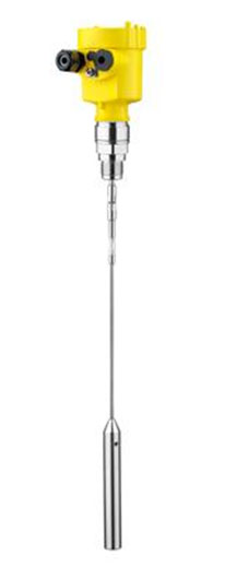
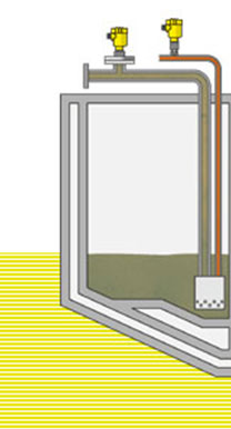
High frequency microwave pulses are coupled on a cable or rod and guided along the probe. The pulses are reflected by the product surface and received by the processing electronics. A microcomputer identifies these level echoes which are measured, evaluated and converted into level information by the ECH software.

Thanks to this measuring principle, the adjustment with the medium is no longer necessary. The instruments are preset to the ordered probe length.

The cable and rod versions (shortable) can be adapted locally to the individual conditions.

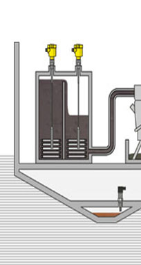
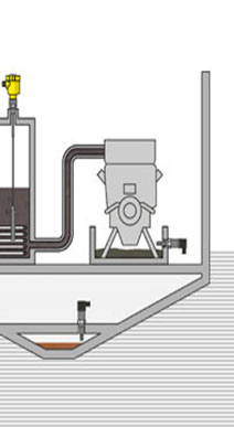
Insensitive to dust, steam and product fluctuations
Even process conditions such as high dust and noise generation or very steamy atmospheres do not influence the accuracy of the measurement. Density fluctuations, different granulation sizes or even fluidization do not influence the accuracy. Even changes from dry to wet gravel are no problem.

Strong buildup on the probe or the vessel wall does not influence the measurement result.

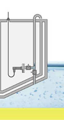
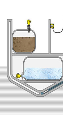
Interface measurement in liquids

Apart from the continuous level measurement of solids and liquids, the principle of the guided microwave was further developed for interface measurement.

Typical applications are measurement of oil and water or solvents and water. 

The microwave pulse is guided along a rod or rope and reflected by an interface with different dielectric value. The advantage compared to displacers and floats is that the measuring principle is independent of the density and does not use any moving parts.

Maintenance-free operation is therefore guaranteed.
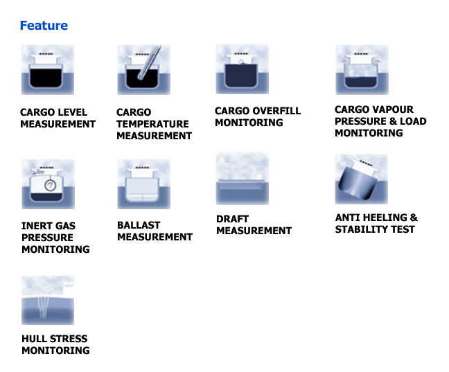
Applications

- Level measurement of solids and liquids

Advantages in an overview

- setup without adjustment
- independent of product features
- insensitive to dust, vapour and buildup
- probes can be shortened
- signal processing ECH for echo analysis with Fuzzy-Logic
- instrument from the plics® family 

Version

with exchangeable cable (ø 4 mm) or rod (ø 6 mm)

Measuring range

cable: up to 32 m
rod: up to 4 m

Process fitting

from G ¾ A

Process temperature

-40…150°C

Process pressure

-1…40 bar
(-100…4000 KPa)

Accuracy

+/- 5 mm


Hydrostatic Pressure
 

In the case where the fluid is at rest, called fluid statics or hydrostatics (from hydro meaning "water" and static meaning "at rest"), the force acting on the object is the sheer weight of the fluid above, up to the water's surface—such as from a water tower. The resulting hydrostatic pressure (static pressure) is isotropic: the pressure acts in all directions equally, according to Pascal's law: 

Our pressure transmitters work acc. to the hydrostatic measuring principle, which functions independently of the dielectric properties of the product and is not influenced by foam generation.

The sensor element of is the dry ceramic-capacitive CERTEC® measuring cell, Stainless Steel, Titanium etc. Base element and diaphragm consist of high purity sapphire-ceramic. The hydrostatic pressure of the product causes via the diaphragm a Capacitance change in the measuring cell. This capacitance change is converted into an appropriate output signal On board vessel, it is well suited for Ballast tanks whereby submersion in seawater do not affect the long term accuracy of the transmitter.

Advantages in an overview

- long term stability 0.1%/2 years
- two wire system 4...20mA
- diameter of the transmitter 32 mm
- integrated overvoltage protection 

Measuring cell

SS316 etc

Cable material

PE/PUR/FEP

Diameter

32 mm

Product temperature

up to 85°C


Shipboard Applications
 

Protection on-board and dock equipment

Monitoring the pipeline pressures at the manifold ensures the safety of on-board and dock equipment, and provides the basis for pump control. If pump output is too high or if valves remain closed during charging and discharging processes, gauge or low pressure in the product pipelines can result.

This can damage the manifold or the storage tanks. On-site pressure indication provides additional security for processes involving the manifold. Choosing an appropriate pressure instrument becomes therefore crucial for this particular application whereby location indication is just as important as remote readout


Draught, trim and list

The most important measurements on board are the measuring points for calculating draught, trim and list. Ship safety depends heavily on them. Using the transmitted values from the different measuring points, the load master, as part of the cargo control system (CCS), can determine the exact values of ship orientation and draught.

Usually, two measuring points forepeak and two additional measuring points afterpeak are used.

Instruments with appropriate protection of IP68 will have to used for this application.


Service and settling tank

To ensure fuel feed to the main engine, the separated heavy fuel oil (HFO) is first pumped into the settling tank (buffer tank).

The connected service tank (day tank) is filled via continuous overflow from the settling tank and is connected directly with the main engine. Heating coils in both tanks ensure an even temperature between +75° and +90°C (+167° and +194°F) which keeps the oil pumpable.

Choosing the correct apparatus that can withstand the high temperature and sludge environment is therefore very important for the long term life of the apparatus. We would recommend an equipment which has minimum contact to the heat and heavy oil, as a guided radar instrument.


Monitoring the bilge

Every motorised ship has a so-called bilge well, i.e. a space between the floor of the engine room and the bottom of the ship. A water/oil mixture collects in this space at the lowest point of the ship. The mixture is then separated into water and oil by an on-board skimmer and demulsifying unit. After passing through various cleaning processes, the water can be pumped out. The bilge de-oiling equipment is controlled by level switches Bloomfoss recommends highly reliable level switch for this application to minimize the changing of this instrument over long periods


Fresh water and grey/black water

Fresh water is an essential commodity on a ship. It is stored in separate dedicated tanks. Depending on the type and size of the ship, different amounts of fresh water are required for drinking, for personal hygiene as well as for cleaning. The amount of water stored in the tanks can be from 50 to 400 tons and depends largely on whether the ship has a desalinisation plant. Direct electrical measuring principles are mandatory for level measurement. Waste water, so-called grey/black water, is treated on large ships in on-board clarification plants, or stored in special grey/black water tanks to await final disposal.

Grey water measurement

Due to the large concentration of solids and the changing density of the tank contents, non-contact measurement with ultrasonic technology qualifies well for this application

Fresh water measurement

Bloomfoss recommends flange side-mounted instruments for fresh water applications. Flanged directly onto the tank, level can be measured reliably and accurately. Materials approved for drinking water and a front-flush diaphragm form the basis of a flawlessly hygienic measurement.